

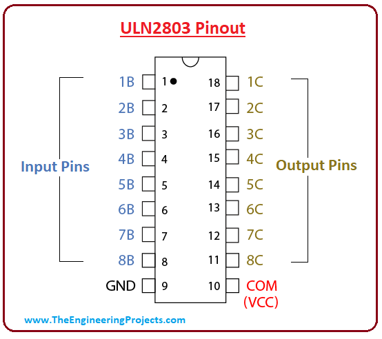
I have merged the topics maybe will make more sense.
I the first part of the video the guy is using an active HIGH relay board (red) and this module doesn't works with this type of board as shown on video.
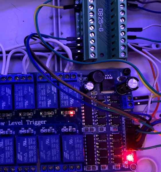
With active LOW boards (blue) the relay are triggered correctly and we can hear the typical "click" from relays.
Forum ‹ Members section ‹ DIY Ferduino controller ‹ Pcf8575 problem
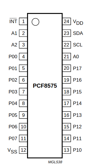
Try measure the voltage directly over the IC (PCF8575) between P00 (pin 4) and GND if it has the same result the module is not working or Arduino is not communicating with PCF correctly.
If over the IC has voltage so the problem is in bad header soldering as pointed previously.
Pcf8575 problem [SOLVED]
70 posts
• Page 3 of 4 • 1, 2, 3, 4
Post Number:#41
 Sat Dec 21, 2019 5:52 pm
Posts: 1699
Topics: 38 Images: 301 Solve rating: 233 Joined: Mon Mar 03, 2014 5:59 pm Topics: 38
Age: 40 Location: São Paulo Gender: 
National Flag:

Post your doubts on forum because it can help another user too. Just PM me for support if it's absolutely necessary.
Post Number:#42
Mon Dec 23, 2019 1:08 pm

Posts: 24
Topics: 7 Images: 5 Solve rating: 0 Joined: Wed Dec 05, 2018 5:23 pm Topics: 7
Age: 43 Gender: 
National Flag:

hi Fernando and Jose,
I tried to connect everything as in the video.
if I connect the pcf8575 directly to the low level relay everything works but if I connect the high level relay through the uln2803a it doesn't work.
I hope the video is clear enough and sorry for the mess of the wires!
I attach another video where everything works with the other model of pcf8575.
I hope I was helpful
 Watch on youtube.com
Watch on youtube.com
regards
I tried to connect everything as in the video.
if I connect the pcf8575 directly to the low level relay everything works but if I connect the high level relay through the uln2803a it doesn't work.
I hope the video is clear enough and sorry for the mess of the wires!
I attach another video where everything works with the other model of pcf8575.
I hope I was helpful
regards
Post Number:#43
Mon Dec 23, 2019 1:21 pm
Posts: 1699
Topics: 38 Images: 301 Solve rating: 233 Joined: Mon Mar 03, 2014 5:59 pm Topics: 38
Age: 40 Location: São Paulo Gender: National Flag:
Hi!
Gio, HIGH level relay board won't work with ULN because the signal is 0V (GND).
I have explained it here a few times. Please check this topic: https://ferduino.com/forum/viewtopic.php?f=6&t=100
Best regards.
if I connect the high level relay through the uln2803a it doesn't work
Gio, HIGH level relay board won't work with ULN because the signal is 0V (GND).
I have explained it here a few times. Please check this topic: https://ferduino.com/forum/viewtopic.php?f=6&t=100
Best regards.
Post your doubts on forum because it can help another user too. Just PM me for support if it's absolutely necessary.
Post Number:#44
Mon Dec 23, 2019 3:15 pm
Posts: 65
Topics: 18 Images: 32 Solve rating: 0 Joined: Fri Jun 16, 2017 6:23 am Topics: 18
Age: 62 Gender: National Flag:

I got confused in the previous answer.
I confirm that if I do not use the uln2803 and connect as in the video the relays get excited and work.
If I pass them through the ULN2803 then it is when the relays are dimmed and not excited.
I confirm that if I do not use the uln2803 and connect as in the video the relays get excited and work.
If I pass them through the ULN2803 then it is when the relays are dimmed and not excited.
Post Number:#45
Mon Dec 23, 2019 5:22 pm
Posts: 24
Topics: 7 Images: 5 Solve rating: 0 Joined: Wed Dec 05, 2018 5:23 pm Topics: 7
Age: 43 Gender: National Flag:
hi,
happens to me exact the same thing that happens to Jose
regards
happens to me exact the same thing that happens to Jose
regards
Post Number:#46
Mon Dec 23, 2019 5:31 pm
Posts: 1699
Topics: 38 Images: 301 Solve rating: 233 Joined: Mon Mar 03, 2014 5:59 pm Topics: 38
Age: 40 Location: São Paulo Gender: National Flag:
ULN can't be used with HIGH level trigger relay board.
But I don't think it's your case because your relay board is LOW level trigger as shown here.
Here you told me that the relays are activated when pins 1 to 16 are connected to GND so the relays are really LOW level trigger.
Maybe you are placing the ULN in wrong position.
But I don't think it's your case because your relay board is LOW level trigger as shown here.
Here you told me that the relays are activated when pins 1 to 16 are connected to GND so the relays are really LOW level trigger.
Maybe you are placing the ULN in wrong position.
Post your doubts on forum because it can help another user too. Just PM me for support if it's absolutely necessary.
Post Number:#47
Mon Dec 23, 2019 6:38 pm
Posts: 65
Topics: 18 Images: 32 Solve rating: 0 Joined: Fri Jun 16, 2017 6:23 am Topics: 18
Age: 62 Gender: National Flag:
I don't know if it can be seen correctly but the ULNs are positioned as shown in the photo (the notch of the integrated one on the left). it's not like that?
Last edited by Fernando Garcia on Mon Dec 23, 2019 6:44 pm, edited 1 time in total.
Reason: Please post images using the tags [img=left][/img]
Reason: Please post images using the tags [img=left][/img]
Post Number:#48
Mon Dec 23, 2019 6:58 pm
Posts: 1699
Topics: 38 Images: 301 Solve rating: 233 Joined: Mon Mar 03, 2014 5:59 pm Topics: 38
Age: 40 Location: São Paulo Gender: National Flag:
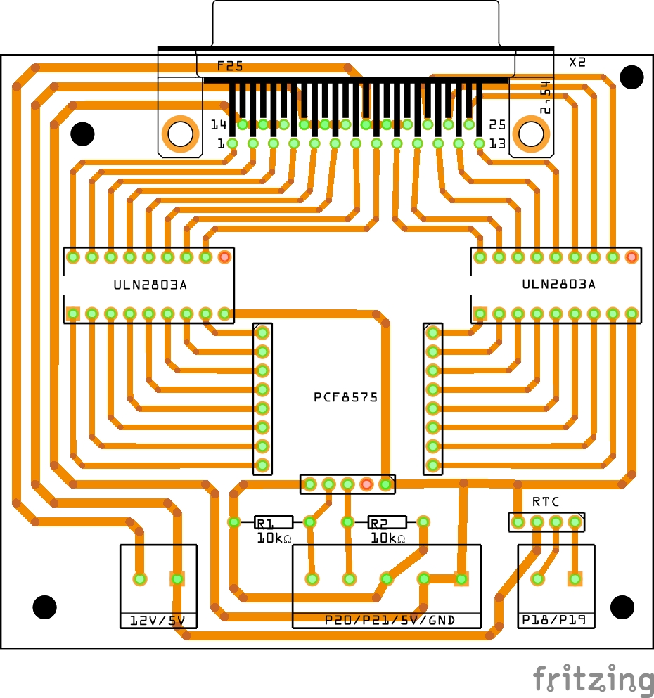
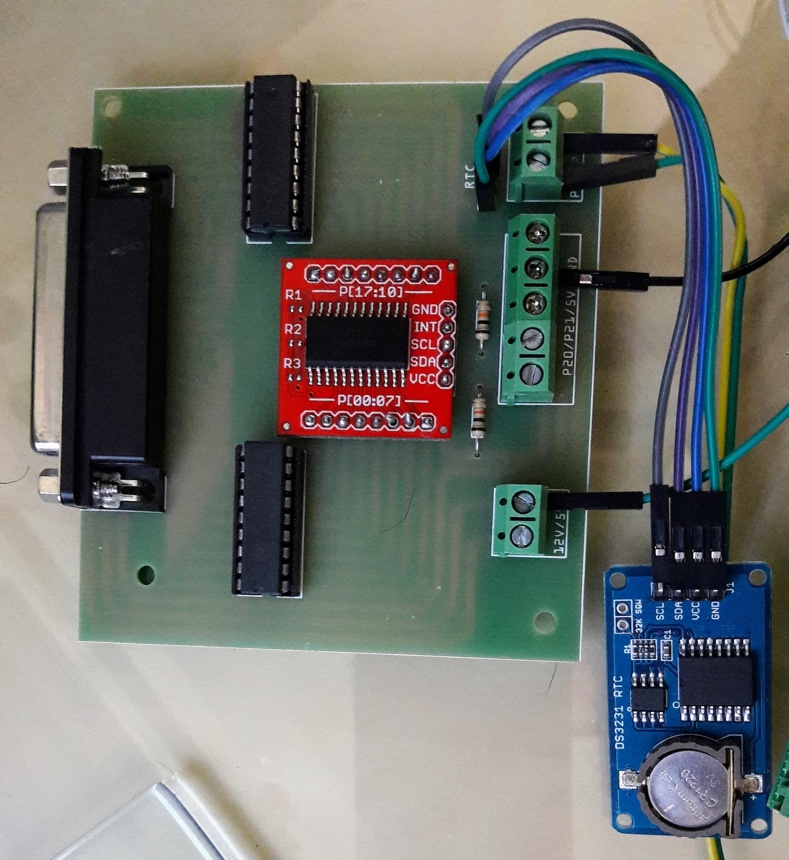
The headers on PCF module seems poorly soldered here:
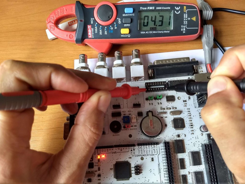
Can you remove the ULN from socket and measure the voltage between pins 1-8 on socket and GND with PCF signal HIGH? It should be around 5 v.
After can you measure the voltage between 5 V and pins 11-18 on socket with PCF signal HIGH? It should be around 5 V too.
Can you remove the ULN from socket and measure the voltage between pins 1-8 on socket and GND with PCF signal HIGH? It should be around 5 v.
After can you measure the voltage between 5 V and pins 11-18 on socket with PCF signal HIGH? It should be around 5 V too.
Post your doubts on forum because it can help another user too. Just PM me for support if it's absolutely necessary.
Post Number:#49
Tue Dec 24, 2019 5:06 am
Posts: 65
Topics: 18 Images: 32 Solve rating: 0 Joined: Fri Jun 16, 2017 6:23 am Topics: 18
Age: 62 Gender: National Flag:
If I try HIGH
Between pins 1-8 and 5V measures 0 V
Between pin 9 (GND) and 5 V it measures 4.96 V
Between pins 11-18 and 5 V it measures 0 V
Between pin 10 (COM) GND measures 0 V
But if I try LOW
Between pins 1-8 and 5 V measures 4.96 V
Between pin 9 (GND) and 5 V it measures 4.96 V
Between pins 11-18 and 5 V gives 0 V
Between pin 10 (COM) and GND gives 0 V
Code: Select all
for (int i = 0; i <15; i ++)
   {
     PCF8575.digitalWrite (i, HIGH); // Tun on all pin
   }
Between pins 1-8 and 5V measures 0 V
Between pin 9 (GND) and 5 V it measures 4.96 V
Between pins 11-18 and 5 V it measures 0 V
Between pin 10 (COM) GND measures 0 V
But if I try LOW
Code: Select all
  for (int i = 0; i <15; i ++)
   {
     PCF8575.digitalWrite (i, LOW); // Turn off all pin
   }
Between pins 1-8 and 5 V measures 4.96 V
Between pin 9 (GND) and 5 V it measures 4.96 V
Between pins 11-18 and 5 V gives 0 V
Between pin 10 (COM) and GND gives 0 V
Post Number:#50
Tue Dec 24, 2019 10:31 am
Posts: 1699
Topics: 38 Images: 301 Solve rating: 233 Joined: Mon Mar 03, 2014 5:59 pm Topics: 38
Age: 40 Location: São Paulo Gender: National Flag:
Hi!
Two mistakes here.
I did not told to measure in this way. Basically you are measuring between 5 V and 5 V, it won't give any voltage obviously because there's no potential difference.
What I told was:
Between pins 1-8 and GND (pin 9) it should give around 5 V as I told before.
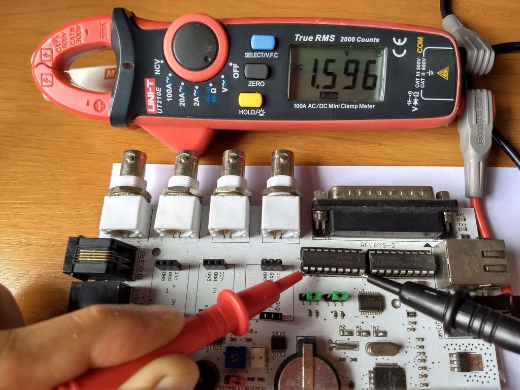
As I told here with ULN connected the voltage should be around 1.5 V.
Here my question is incomplete. I forgot to say to put the ULN back on socket before measure.
Without ULN the socket pin is connected only to DB25 and it will give 0~1 V only.
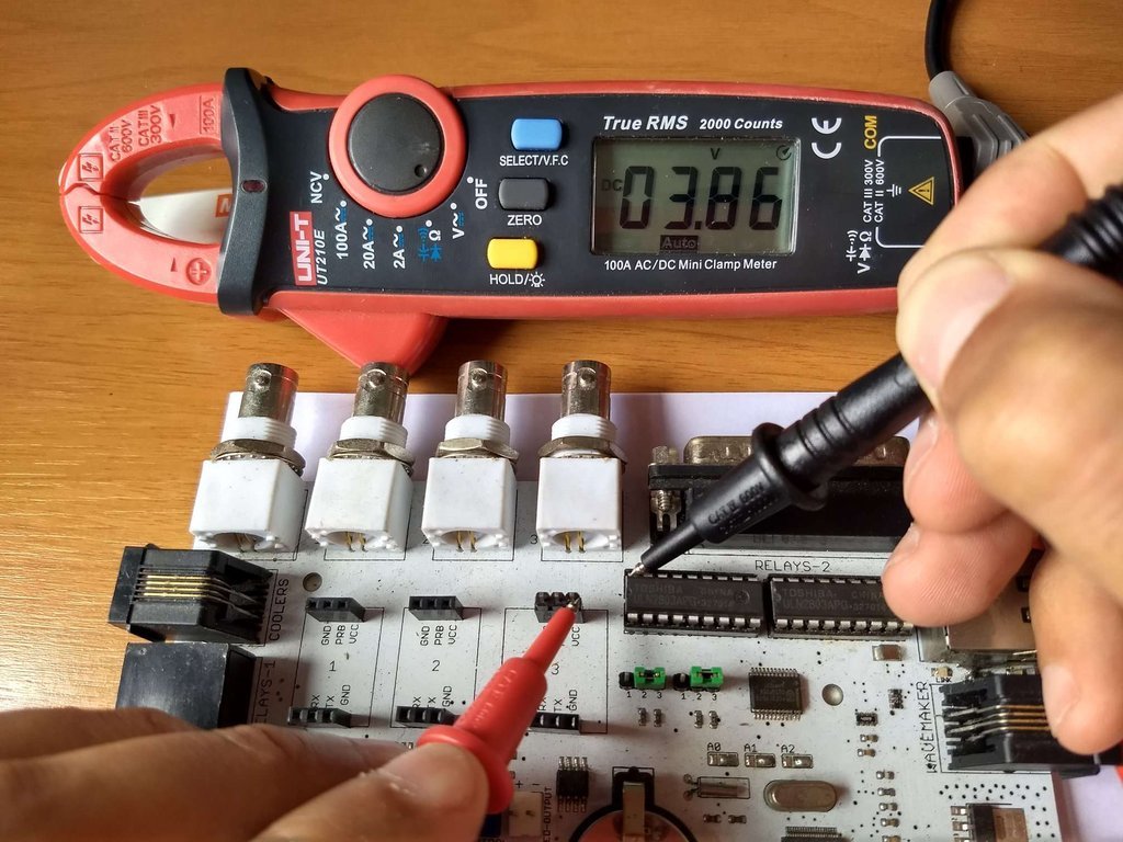
With ULN connected between pin 11-18 should give around 5 V as I told before.
This test is not needed and will make the things more complicated here.
Best regards.
Two mistakes here.
Between pins 1-8 and 5V measures 0 V
I did not told to measure in this way. Basically you are measuring between 5 V and 5 V, it won't give any voltage obviously because there's no potential difference.
What I told was:
measure the voltage between pins 1-8 on socket and GND
Between pins 1-8 and GND (pin 9) it should give around 5 V as I told before.
As I told here with ULN connected the voltage should be around 1.5 V.
Code: Select all
After can you measure the voltage between 5 V and pins 11-18 on socket with PCF signal HIGH? It should be around 5 V too.Here my question is incomplete. I forgot to say to put the ULN back on socket before measure.
Without ULN the socket pin is connected only to DB25 and it will give 0~1 V only.
With ULN connected between pin 11-18 should give around 5 V as I told before.
Code: Select all
But if I try LOWThis test is not needed and will make the things more complicated here.
Best regards.
Post your doubts on forum because it can help another user too. Just PM me for support if it's absolutely necessary.
Post Number:#51
Tue Dec 24, 2019 1:24 pm
Posts: 65
Topics: 18 Images: 32 Solve rating: 0 Joined: Fri Jun 16, 2017 6:23 am Topics: 18
Age: 62 Gender: National Flag:
Apologies for not understanding how to perform the tests.
With HIGH pins with both ULN and without it between 1-8 and GND (9) it measures 0 V
With HIGH pins with both ULN and without it between 11-18 and 5 V it measures 0 V
With HIGH pins with both ULN and without it between 1-8 and GND (9) it measures 0 V
With HIGH pins with both ULN and without it between 11-18 and 5 V it measures 0 V
Post Number:#52
Tue Dec 24, 2019 2:10 pm
Posts: 1699
Topics: 38 Images: 301 Solve rating: 233 Joined: Mon Mar 03, 2014 5:59 pm Topics: 38
Age: 40 Location: São Paulo Gender: National Flag:
With HIGH pins with both ULN and without it between 1-8 and GND (9) it measures 0 V
Try measure the voltage directly over the IC (PCF8575) between P00 (pin 4) and GND if it has the same result the module is not working or Arduino is not communicating with PCF correctly.
If over the IC has voltage so the problem is in bad header soldering as pointed previously.
Post your doubts on forum because it can help another user too. Just PM me for support if it's absolutely necessary.
Post Number:#53
Tue Dec 24, 2019 4:08 pm
Posts: 24
Topics: 7 Images: 5 Solve rating: 0 Joined: Wed Dec 05, 2018 5:23 pm Topics: 7
Age: 43 Gender: National Flag:
Post Number:#54
Tue Dec 24, 2019 4:56 pm
Posts: 1699
Topics: 38 Images: 301 Solve rating: 233 Joined: Mon Mar 03, 2014 5:59 pm Topics: 38
Age: 40 Location: São Paulo Gender: National Flag:
Gio, pictures and texts should be more useful.
This video has bad quality (480p) and it's very short. Moreover I don't know your PCB.
When the multimeter is showing negative voltage is because the polarity is inverted. You should swap probes positions.
BTW, making videos in landscape is always the best choice.
This video has bad quality (480p) and it's very short. Moreover I don't know your PCB.
When the multimeter is showing negative voltage is because the polarity is inverted. You should swap probes positions.
BTW, making videos in landscape is always the best choice.
- Off Topic
- Gio, I see your pics about the problem with web interface. I have fixed this bug, please check it. Thanks for it!
Post your doubts on forum because it can help another user too. Just PM me for support if it's absolutely necessary.
Post Number:#55
Tue Dec 24, 2019 8:12 pm
Posts: 24
Topics: 7 Images: 5 Solve rating: 0 Joined: Wed Dec 05, 2018 5:23 pm Topics: 7
Age: 43 Gender: National Flag:
Off topic!
Thank you Fernando.
I hadn't had time to write to you! Now everything is perfect!
Thank you Fernando.
I hadn't had time to write to you! Now everything is perfect!
Post Number:#56
Wed Dec 25, 2019 6:14 am
Posts: 65
Topics: 18 Images: 32 Solve rating: 0 Joined: Fri Jun 16, 2017 6:23 am Topics: 18
Age: 62 Gender: National Flag:
Merry Christmas !!!
My knowledge of electronics is very limited so I go blind and I can only move forward thanks to your help Fernando.
Performing measurements as indicated (from the PCF8575 pin to GND) the result is 0 V.
What I don't understand is that if I don't use the ULN modules it seems to work correctly.
Watch on youtube.com
Even if I bypass the ULN socket also works.
Watch on youtube.com
Thanks
My knowledge of electronics is very limited so I go blind and I can only move forward thanks to your help Fernando.
Performing measurements as indicated (from the PCF8575 pin to GND) the result is 0 V.
What I don't understand is that if I don't use the ULN modules it seems to work correctly.
Even if I bypass the ULN socket also works.
Thanks
Post Number:#57
Wed Dec 25, 2019 2:28 pm
Posts: 1699
Topics: 38 Images: 301 Solve rating: 233 Joined: Mon Mar 03, 2014 5:59 pm Topics: 38
Age: 40 Location: São Paulo Gender: National Flag:
Hi!
Merry christmas for all!
For some reason this module is not working as OUTPUT just as INPUT.
You can notice that relay is just turned on when a LOW command is sent.
The solution could be bypass the ULN and change on code LOW to HIGH and HIGH to LOW.
But I'm not sure if PCF can manage the current of all relays.
Try this code bypassing the ULN and check the behaviour and serial monitor.
Edit:
If the circuit is working as I told above to prevent damage PCF I think that ULN could be replaced by a PNP transistor array and TD62384AP seems suitable.
Best regards.
Merry christmas for all!
For some reason this module is not working as OUTPUT just as INPUT.
You can notice that relay is just turned on when a LOW command is sent.
The solution could be bypass the ULN and change on code LOW to HIGH and HIGH to LOW.
But I'm not sure if PCF can manage the current of all relays.
Try this code bypassing the ULN and check the behaviour and serial monitor.
Code: Select all
#include "mxUnifiedPCF8574.h"

mxUnifiedPCF8575 PCF8575 = mxUnifiedPCF8575(0x20); // Endereço em hexadecimal = 0x20

void setup()
{
  Serial.begin(9600);
  while(!Serial)
  {
    ;
  }
  Serial.println("I'm alive!");

  PCF8575.begin();

  for(int i = 0; i < 16; i++)
  {
    PCF8575.pinMode(i,OUTPUT);
  }
}

void loop()
{
   Serial.println("\n\nTuning OFF all relays");
  for(int i = 0; i < 16; i++)
  {
    PCF8575.digitalWrite(i, HIGH); // Tun on all pins
    delay(200);
    Serial.print("pin ");
    Serial.print(i);
    Serial.print(": ");
    Serial.println(PCF8575.digitalRead(i) ? "HIGH" : "LOW");
  }
  delay(5000);

  Serial.println("\n\nTuning ON all relays");

  for(int i = 0; i < 16; i++)
  {
    PCF8575.digitalWrite(i, LOW); // Turn off all pins
    delay(200);
    Serial.print("pin ");
    Serial.print(i);
    Serial.print(": ");
    Serial.println(PCF8575.digitalRead(i) ? "HIGH" : "LOW");
  }
  delay(5000);
}
Edit:
If the circuit is working as I told above to prevent damage PCF I think that ULN could be replaced by a PNP transistor array and TD62384AP seems suitable.
Best regards.
Last edited by Fernando Garcia on Wed Dec 25, 2019 3:05 pm, edited 1 time in total.
Reason: Fix info in edit.
Reason: Fix info in edit.
Post your doubts on forum because it can help another user too. Just PM me for support if it's absolutely necessary.
Post Number:#58
Wed Dec 25, 2019 7:49 pm
Posts: 65
Topics: 18 Images: 32 Solve rating: 0 Joined: Fri Jun 16, 2017 6:23 am Topics: 18
Age: 62 Gender: National Flag:
It behaves as you say, following the output to the serial monitor the relays turn on in LOW and turn off in HIGH.
I had to compile the code with the PCF8575.h library since with the mxUnifiedPCF8574.h it gives me a compilation error (I have previously installed the library).
As seen in the video, the 16 relays light up.
Watch on youtube.com
To take advantage of the PCB that I have already manufactured, do you think the system will work by removing the ULN and bypassing the socket? (in addition to modifying in the code HIGH pot LOW and LOW by HIGH).
Is it possible to acquire somewhere the PCF module that behaves in reverse mode?.
I had to compile the code with the PCF8575.h library since with the mxUnifiedPCF8574.h it gives me a compilation error (I have previously installed the library).
As seen in the video, the 16 relays light up.
To take advantage of the PCB that I have already manufactured, do you think the system will work by removing the ULN and bypassing the socket? (in addition to modifying in the code HIGH pot LOW and LOW by HIGH).
Is it possible to acquire somewhere the PCF module that behaves in reverse mode?.
Post Number:#59
Wed Dec 25, 2019 10:31 pm
Posts: 1699
Topics: 38 Images: 301 Solve rating: 233 Joined: Mon Mar 03, 2014 5:59 pm Topics: 38
Age: 40 Location: São Paulo Gender: National Flag:
You should find a module with a PCF8575TS instead PCF8575C.
Ferduino Mega and blue module has TS type. Should have some difference betweem TS and C type.
If you can't find this type can buy only the IC and replace on red module.
Ferduino Mega and blue module has TS type. Should have some difference betweem TS and C type.
If you can't find this type can buy only the IC and replace on red module.
Post your doubts on forum because it can help another user too. Just PM me for support if it's absolutely necessary.
Post Number:#60
Thu Dec 26, 2019 4:12 am
Posts: 65
Topics: 18 Images: 32 Solve rating: 0 Joined: Fri Jun 16, 2017 6:23 am Topics: 18
Age: 62 Gender: National Flag:
I do not find the PCF8575TS module mounted and the truth is that I am not able to replace the integrated module on the red module.
Is it possible to work simply by removing the ULN2803 and bypassing the sockets? Apparently it seems so, but I don't know if the use could cause problems.
Thank you and at least I know what the problem was.
Is it possible to work simply by removing the ULN2803 and bypassing the sockets? Apparently it seems so, but I don't know if the use could cause problems.
Thank you and at least I know what the problem was.
70 posts
• Page 3 of 4 • 1, 2, 3, 4
Return to DIY Ferduino controller
Who is online
Users viewing this topic: No registered users and 3 guests