
I finally decided to go with this driver. If i decide to add one more led, i can do it right?
Is there so much difference from 500h ldd?
Some quick questions:
I have the following arduino hardware:
1. Arduino Compatible Atmega2560-16AU CH340G ATMEGA 2560 R3 Board Mega2560 R3
2. http://www.ebay.com/itm/121114423145
3. http://www.ebay.com/itm/311519653531
4. http://www.ebay.com/itm/142087550541
5. http://www.ebay.com/itm/331799616470
6. http://www.ebay.com/itm/262423841770
7. http://www.ebay.com/itm/361742868985
Do i need something exta?
Forum ‹ Members section ‹ LED light and others ‹ 5 channel Multichip full spectrum LED help
5 channel Multichip full spectrum LED help [SOLVED]
39 posts
• Page 2 of 2 • 1, 2
Post Number:#21
 Fri Jan 06, 2017 4:54 pm
Posts: 69
Topics: 4 Images: 13 Solve rating: 0 Joined: Tue Jan 03, 2017 9:34 pm Topics: 4
Age: 49 Gender: 
National Flag:

Post Number:#22
Fri Jan 06, 2017 5:36 pm


Posts: 1699
Topics: 38 Images: 301 Solve rating: 233 Joined: Mon Mar 03, 2014 5:59 pm Topics: 38
Age: 39 Location: São Paulo Gender: National Flag:

Using the maximum current the life time of your LED will be smaller as I told before.
Only this parts can be used, all others except Arduino are incompatible with Ferduino code.
http://www.ebay.com/itm/262423841770
http://www.ebay.com/itm/331799616470
Maybe you can use this TFT shield with an external RTC but I think better buy and assembly a kit with RTC.
Please check my part list.
viewtopic.php?f=24&t=39
Post your doubts on forum because it can help another user too. Just PM me for support if it's absolutely necessary.
Post Number:#23
Fri Jan 06, 2017 6:04 pm
Posts: 69
Topics: 4 Images: 13 Solve rating: 0 Joined: Tue Jan 03, 2017 9:34 pm Topics: 4
Age: 49 Gender: National Flag:
So Only for lighting (for start) what extra need to buy?
Post Number:#24
Fri Jan 06, 2017 7:00 pm
Posts: 1699
Topics: 38 Images: 301 Solve rating: 233 Joined: Mon Mar 03, 2014 5:59 pm Topics: 38
Age: 39 Location: São Paulo Gender: National Flag:
TFT + TFT shield with RTC.
Post your doubts on forum because it can help another user too. Just PM me for support if it's absolutely necessary.
Post Number:#25
Sat Jan 07, 2017 6:14 am
Posts: 69
Topics: 4 Images: 13 Solve rating: 0 Joined: Tue Jan 03, 2017 9:34 pm Topics: 4
Age: 49 Gender: National Flag:
For lowering the cost, is it possible to use 4 5-ldd boards?
Post Number:#26
Sat Jan 07, 2017 7:38 am
Posts: 1699
Topics: 38 Images: 301 Solve rating: 233 Joined: Mon Mar 03, 2014 5:59 pm Topics: 38
Age: 39 Location: São Paulo Gender: National Flag:
Hi!
In a board all V+ are linked so you will have to cut the trail of one LDD to connect 26V to channel 4 and solder the wire in the board.
Best regards.
-------------------------------- Last edited Sat Jan 07, 2017 9:01 am --------------------------------
Connecting the step down between the power supply and black connector all LDDs will work with 26V but you will need of 1 LDD working at 36V to complete 16 channels at 36V. For it will be needed cut the trail to connect 1 wire with 36V.
Post your doubts on forum because it can help another user too. Just PM me for support if it's absolutely necessary.
Post Number:#28
Tue Jan 10, 2017 9:21 am
Posts: 1699
Topics: 38 Images: 301 Solve rating: 233 Joined: Mon Mar 03, 2014 5:59 pm Topics: 38
Age: 39 Location: São Paulo Gender: National Flag:
Hi!
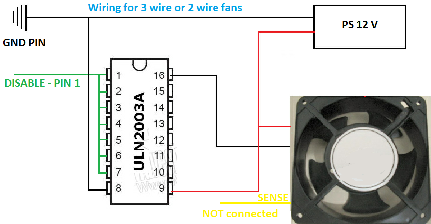
The Fans should have PWM control, normally have 4 wires.
I recommend buy fans from Arctic because are very quiet.
You can buy this model and replace the fans for this: https://www.arctic.ac/worldwide_en/arctic-f9-pwm.html
Or buy the kit from Arctic: https://www.arctic.ac/worldwide_en/acce ... -6990.html
Best regards.
Post your doubts on forum because it can help another user too. Just PM me for support if it's absolutely necessary.
Post Number:#30
Tue Jan 10, 2017 11:58 am
Posts: 1699
Topics: 38 Images: 301 Solve rating: 233 Joined: Mon Mar 03, 2014 5:59 pm Topics: 38
Age: 39 Location: São Paulo Gender: National Flag:
This heatsink is rated to 120W it could be enough but this surface to fix the LED seems not big enough. I can't see any dimension for it.

Post your doubts on forum because it can help another user too. Just PM me for support if it's absolutely necessary.
Post Number:#31
Wed Jan 11, 2017 8:28 am
Posts: 69
Topics: 4 Images: 13 Solve rating: 0 Joined: Tue Jan 03, 2017 9:34 pm Topics: 4
Age: 49 Gender: National Flag:
Is necessary the PWM control for the fans? Can i use constant RPM?
Post Number:#32
Wed Jan 11, 2017 8:42 am
Posts: 1699
Topics: 38 Images: 301 Solve rating: 233 Joined: Mon Mar 03, 2014 5:59 pm Topics: 38
Age: 39 Location: São Paulo Gender: National Flag:
Hi!
PWM control is optional.
Best regards.
PWM control is optional.
Best regards.
Post your doubts on forum because it can help another user too. Just PM me for support if it's absolutely necessary.
Post Number:#34
Wed Jan 11, 2017 9:17 am
Posts: 1699
Topics: 38 Images: 301 Solve rating: 233 Joined: Mon Mar 03, 2014 5:59 pm Topics: 38
Age: 39 Location: São Paulo Gender: National Flag:
All informations needed are on forum, search a bit please.
Post your doubts on forum because it can help another user too. Just PM me for support if it's absolutely necessary.
Post Number:#35
Wed Jan 11, 2017 9:35 am
Posts: 69
Topics: 4 Images: 13 Solve rating: 0 Joined: Tue Jan 03, 2017 9:34 pm Topics: 4
Age: 49 Gender: National Flag:
Sory.... but all those diagrams seems Greek to me!!!!! 
Post Number:#36
Wed Jan 11, 2017 9:56 am
Posts: 1699
Topics: 38 Images: 301 Solve rating: 233 Joined: Mon Mar 03, 2014 5:59 pm Topics: 38
Age: 39 Location: São Paulo Gender: National Flag:
So it's good should be VERY EASY for you.
Post your doubts on forum because it can help another user too. Just PM me for support if it's absolutely necessary.
Post Number:#37
Thu Jan 19, 2017 3:45 pm
Posts: 69
Topics: 4 Images: 13 Solve rating: 0 Joined: Tue Jan 03, 2017 9:34 pm Topics: 4
Age: 49 Gender: National Flag:
Hi,
I've finally ordered all the nessesary parts and i'm trying to figure out how to wire them. From what i can understand:
1. I have to connect each ldd Board whith the power supply. One channel must be wirred to step down regulator.
2. I have to wire all the ground signals from ldd boards in one wire and connect it to arduino's ground
3. I have to to wire the same colors from each led in one wire and connect it to each arduino's color signal.
It's a lttle bit confusing to me. Some suggest to put a 10k resistor in each color signal. I think tha i need a simple diagram, even handwritten. I suppose that i'll need to wire them in pcb Board cause i'll need the ground signal for the other functions.....
Post Number:#38
Thu Jan 19, 2017 4:41 pm
Posts: 1699
Topics: 38 Images: 301 Solve rating: 233 Joined: Mon Mar 03, 2014 5:59 pm Topics: 38
Age: 39 Location: São Paulo Gender: National Flag:
Hi!
Not exactly, you can't connect 34 and 26 V to a board without cut PCB trace. As you can see in the image above there only one black connector to connect the power supply.
What you should make is use 1 LDD board to all channels 4 with step down between the black connector and power supply.
So will left 1 LDD in this board to connect a channel at 34V. As there no black connector for this you should cut the PCB trace that goes to V+ in this LDD and solder the wire with 34V directly on PCB.
Yes.
Yes, if you are talking about connect PWM signal from LDD board in parallel.
This resistor is called PULL DOWN but some LDD board have it in SMD on bottom side like this (R1 to R5):

You have to check in your LDD board.
If it haven't you can put the resistor next of Arduino PWM connector between GND and PWM pin. The schematic is like this:
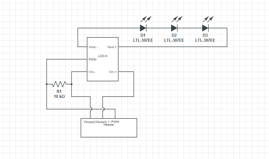
Only to remember V-, GND and GROUND are same thing.
Best regards.
1. I have to connect each ldd Board whith the power supply. One channel must be wirred to step down regulator.
Not exactly, you can't connect 34 and 26 V to a board without cut PCB trace. As you can see in the image above there only one black connector to connect the power supply.
What you should make is use 1 LDD board to all channels 4 with step down between the black connector and power supply.
So will left 1 LDD in this board to connect a channel at 34V. As there no black connector for this you should cut the PCB trace that goes to V+ in this LDD and solder the wire with 34V directly on PCB.
2. I have to wire all the ground signals from ldd boards in one wire and connect it to arduino's ground
Yes.
3. I have to to wire the same colors from each led in one wire and connect it to each arduino's color signal.
Yes, if you are talking about connect PWM signal from LDD board in parallel.
It's a lttle bit confusing to me. Some suggest to put a 10k resistor in each color signal. I think tha i need a simple diagram, even handwritten. I suppose that i'll need to wire them in pcb Board cause i'll need the ground signal for the other functions.....
This resistor is called PULL DOWN but some LDD board have it in SMD on bottom side like this (R1 to R5):
You have to check in your LDD board.
If it haven't you can put the resistor next of Arduino PWM connector between GND and PWM pin. The schematic is like this:
Only to remember V-, GND and GROUND are same thing.
Best regards.
Post your doubts on forum because it can help another user too. Just PM me for support if it's absolutely necessary.
Post Number:#39
Mon Feb 20, 2017 4:34 pm
Posts: 1699
Topics: 38 Images: 301 Solve rating: 233 Joined: Mon Mar 03, 2014 5:59 pm Topics: 38
Age: 39 Location: São Paulo Gender: National Flag:
Hi!
I'm sorry for my misunderstanding and bad words.
I have deleted the last two posts.
I hope see similar action from you.
We can keep talking about this build when you show me your Ferduino controller parts.
Best regards.
I'm sorry for my misunderstanding and bad words.
I have deleted the last two posts.
I hope see similar action from you.
We can keep talking about this build when you show me your Ferduino controller parts.
Best regards.
Post your doubts on forum because it can help another user too. Just PM me for support if it's absolutely necessary.
39 posts
• Page 2 of 2 • 1, 2
Return to LED light and others
Who is online
Users viewing this topic: No registered users and 1 guest