
Fernando
I am adding the potentiometer mod to the TFT shield like you showed in your TFT shield post.
I have a 1K multiturn pot, can I use it for this.
Also, when I test it should I start with the pot turned down low so I have just the 10 ohms from the supplied resistor.
Thank you
Donato
Forum ‹ Members section ‹ DIY Ferduino controller ‹ Potentiometer mod for TFT shield question
Potentiometer mod for TFT shield question [SOLVED]
10 posts
• Page 1 of 1
Post Number:#1
 Tue May 27, 2014 8:43 pm
Posts: 21
Topics: 5 Images: 0 Solve rating: 0 Joined: Sat May 03, 2014 10:00 pm Topics: 5
Age: 60 Gender: 
National Flag:

Post Number:#2
Tue May 27, 2014 8:57 pm


Posts: 1699
Topics: 38 Images: 301 Solve rating: 233 Joined: Mon Mar 03, 2014 5:59 pm Topics: 38
Age: 39 Location: São Paulo Gender: National Flag:

Hi!
You can but maybe you will need of more resistance.
No matter because the voltage never will be higher than 3.3V.
Best regards.
You can but maybe you will need of more resistance.
No matter because the voltage never will be higher than 3.3V.
Best regards.
Post your doubts on forum because it can help another user too. Just PM me for support if it's absolutely necessary.
Post Number:#3
Tue May 27, 2014 10:05 pm
Posts: 21
Topics: 5 Images: 0 Solve rating: 0 Joined: Sat May 03, 2014 10:00 pm Topics: 5
Age: 60 Gender: National Flag:
Fernando
I will try it first and if needed I will go and buy a 10K ohm pot to replace it.
Obrigado
Donato
I will try it first and if needed I will go and buy a 10K ohm pot to replace it.
Obrigado
Donato
Post Number:#4
Thu May 29, 2014 3:45 am


Posts: 23
Topics: 4 Solve rating: 0 Joined: Fri May 09, 2014 6:55 am Topics: 4
Age: 48 Location: Tuscany, Italy Gender: National Flag:

Show us your work when you are done with it 
Post Number:#5
Thu May 29, 2014 10:14 pm
Posts: 21
Topics: 5 Images: 0 Solve rating: 0 Joined: Sat May 03, 2014 10:00 pm Topics: 5
Age: 60 Gender: National Flag:
Simone
I'm still waiting for parts to come in but as soon as I get a chance I'll take a couple of pictures of the TFT shield
I think it has turned out well so far.
Take care
Donato
I'm still waiting for parts to come in but as soon as I get a chance I'll take a couple of pictures of the TFT shield
I think it has turned out well so far.
Take care
Donato
Post Number:#6
Sun Jun 15, 2014 3:24 pm
Posts: 1699
Topics: 38 Images: 301 Solve rating: 233 Joined: Mon Mar 03, 2014 5:59 pm Topics: 38
Age: 39 Location: São Paulo Gender: National Flag:
Hi!
Please, give us a feedback about this question.
Best regards.
Please, give us a feedback about this question.
Best regards.
Post your doubts on forum because it can help another user too. Just PM me for support if it's absolutely necessary.
Post Number:#7
Sun Jun 15, 2014 7:50 pm
Posts: 21
Topics: 5 Images: 0 Solve rating: 0 Joined: Sat May 03, 2014 10:00 pm Topics: 5
Age: 60 Gender: National Flag:
I will
I am going to take some pictures soon and will post them.
I did not want to post my work when I thought I had issues with the shield.
Regards
Donato
I am going to take some pictures soon and will post them.
I did not want to post my work when I thought I had issues with the shield.
Regards
Donato
Post Number:#8
Thu Jun 26, 2014 1:06 am
Posts: 21
Topics: 5 Images: 0 Solve rating: 0 Joined: Sat May 03, 2014 10:00 pm Topics: 5
Age: 60 Gender: National Flag:
Okay, finally got time to get it done so here we go.
First 2 images are how I prepared the potentiometer. I used a 10Kohm potentiometer, since it would add a much smaller load to the Arduino than the 5K, and one of the 10 ohm resistors in the kit.
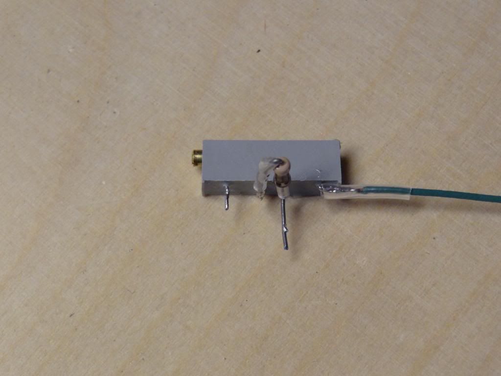
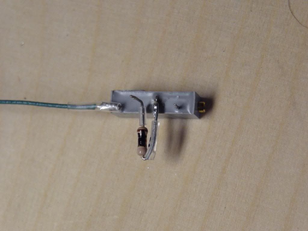
Then I soldered the other 10 ohm resistor on the bottom of the board to allow room for the pot on top.
Then I soldered in the pot and resistor combo. front leg of pot goes in front hole and resistor leg goes in second hole.
third leg with green wire goes to ground pin. Then I used some hotglue to secure the back end of the pot.
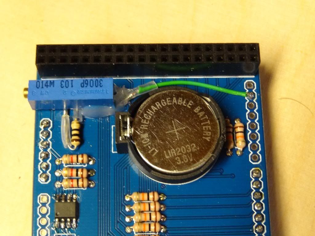
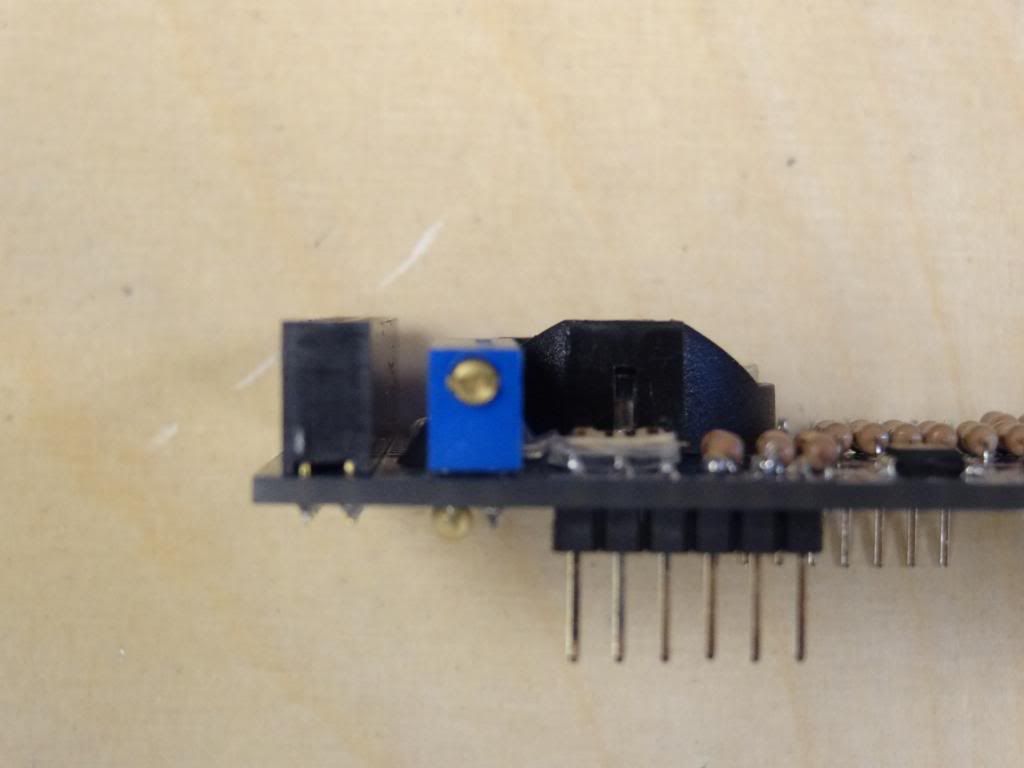
this provided a nice low profile and didn't interfere with the stacking of the shields.
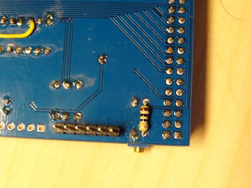
You will also notice that I soldered both legs of R16 to the board but removed pin 53.
I then soldered a wire from the leg of R16 to the leg of R32 that directly connects to pin 4
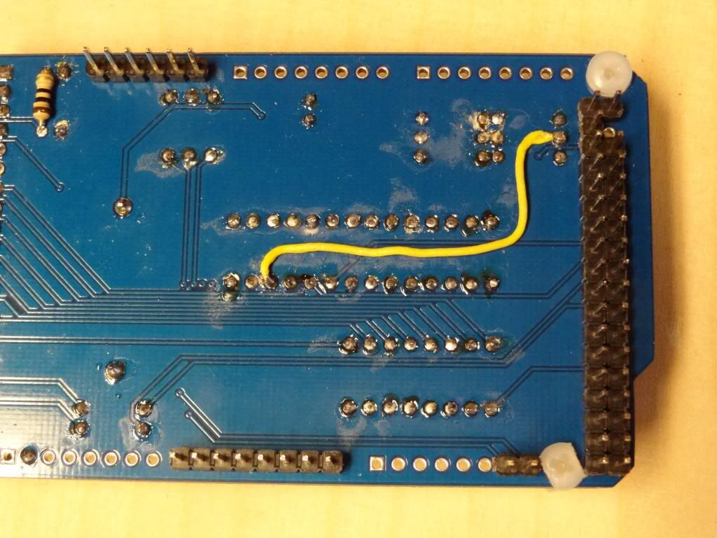
so far so good, board has tested good, though I had to use a IC2 scanner to get my RTC working correctly.
Regards
Donato
First 2 images are how I prepared the potentiometer. I used a 10Kohm potentiometer, since it would add a much smaller load to the Arduino than the 5K, and one of the 10 ohm resistors in the kit.
Then I soldered the other 10 ohm resistor on the bottom of the board to allow room for the pot on top.
Then I soldered in the pot and resistor combo. front leg of pot goes in front hole and resistor leg goes in second hole.
third leg with green wire goes to ground pin. Then I used some hotglue to secure the back end of the pot.
this provided a nice low profile and didn't interfere with the stacking of the shields.
You will also notice that I soldered both legs of R16 to the board but removed pin 53.
I then soldered a wire from the leg of R16 to the leg of R32 that directly connects to pin 4
so far so good, board has tested good, though I had to use a IC2 scanner to get my RTC working correctly.
Regards
Donato
Post Number:#9
Thu Jun 26, 2014 9:52 am
Posts: 1699
Topics: 38 Images: 301 Solve rating: 233 Joined: Mon Mar 03, 2014 5:59 pm Topics: 38
Age: 39 Location: São Paulo Gender: National Flag:
Hi!
Great work!
Thank you by feedback.
Mark this topic as solved if you haven't any problem about this.
Best regards.
Great work!
Thank you by feedback.
Mark this topic as solved if you haven't any problem about this.
Best regards.
Post your doubts on forum because it can help another user too. Just PM me for support if it's absolutely necessary.
Post Number:#10
Thu Jun 26, 2014 7:36 pm

Posts: 68
Topics: 2 Solve rating: 0 Joined: Thu Apr 10, 2014 7:59 pm Topics: 2
Age: 57 Location: Barbourville, Kentucky Gender: National Flag:

excellent work, thank you for sharing
10 posts
• Page 1 of 1
Return to DIY Ferduino controller
Who is online
Users viewing this topic: No registered users and 1 guest