
Hello, I am new to Arduino so I could use some help.
I see there is a parts list here: viewtopic.php?f=24&t=39
Are there any other parts I will need? (I don't have scrap parts around since I have never done this before)
Are these the only circuits I need to know, or are there more?
viewtopic.php?f=24&t=40
viewtopic.php?f=24&t=41
viewtopic.php?f=24&t=36
How do I get it to work with LDD drivers and controllable fans?
Besides those links is there any more information I should know?
Forum ‹ Members section ‹ DIY Ferduino controller ‹ Need some help getting started
Hello, thank you for the help!
I will swich to the TFT + RTC and the LCD that Fernando recommends in the parts list:
TFT shield with RTC
TFT LCD Screen
I will also use the W5100 instead of the Ethernet module.
What is "low level active"? Would these be better relays?
1. A bit confused, do I need x1 or x2 PCF8575?
2. These are the closest things I can find to the relay board on the part list, but they have a reset button on them. Will any of these work?:
http://www.ebay.com/itm/like/3214996107 ... =82&chn=ps
http://www.hobbyking.com/hobbyking/stor ... hield.html
http://www.ebay.com/itm/Blue-Prototype- ... 4897.l4275
3. What MOSFET do I use with 700mA and 1000mA LDD drivers on this power supply?
Many thanks Fernando. I will start a "Show your controller" thread when my parts arrive.
Need some help getting started
14 posts
• Page 1 of 1
Post Number:#1
 Fri Mar 27, 2015 7:39 pm
Posts: 10
Topics: 2 Solve rating: 0 Joined: Thu Mar 26, 2015 3:59 pm Topics: 2
Age: 28 Gender: 
National Flag:

Post Number:#2
Fri Mar 27, 2015 10:28 pm
Posts: 10
Topics: 2 Solve rating: 0 Joined: Thu Mar 26, 2015 3:59 pm Topics: 2
Age: 28 Gender: National Flag:
How do these parts look?
SainSmart Mega2560 + 3.2" TFT LCD Shield + Touch Screen SD Reader for Arduino 2560 Kit
SainSmart I2C RTC DS1307 AT24C32 Real Time Clock (Will this RTC work with the kit above?)
Mini ENC28J60 Ethernet LAN / Network Module
DS18B20 Temperature Temp Sensor
PCF8575 I2C I/O Extension Shield Module
16 Channel 5V Relay Module Board
Ezo pH Stamp
Single Circuit Carrier Board (I only want to measure pH)
Prototype Shield DIY KIT
Jumper Cables
Do I need any jacks, connectors, and boards to attach them too? (I see RedTop here has some float switches on 3.5mm jacks attached to a small board)
Post Number:#3
Sat Mar 28, 2015 12:24 pm
Posts: 5
Topics: 1 Images: 3 Solve rating: 0 Joined: Thu Mar 12, 2015 3:16 pm Topics: 1
Age: 48 Gender: 
National Flag:

Hi!!
I'm not an expert and I am also as you starting with Arduino but will try to help you with something
The libraries used by Ferduino have some conflict with that rtc
The thernet ENC28J60 does not already support you need to find Ethernet W5100
LCD'm not sure if it worked, I think you would have to change code
And if that relays board is low level active, you will need two ULN2803
Best regards and forgive my poor English
Post Number:#4
Sat Mar 28, 2015 4:52 pm
Posts: 10
Topics: 2 Solve rating: 0 Joined: Thu Mar 26, 2015 3:59 pm Topics: 2
Age: 28 Gender: National Flag:
Hi!!
I'm not an expert and I am also as you starting with Arduino but will try to help you with something
The libraries used by Ferduino have some conflict with that rtc
The thernet ENC28J60 does not already support you need to find Ethernet W5100
LCD'm not sure if it worked, I think you would have to change code
And if that relays board is low level active, you will need two ULN2803
Best regards and forgive my poor English
I'm not an expert and I am also as you starting with Arduino but will try to help you with something
The libraries used by Ferduino have some conflict with that rtc
The thernet ENC28J60 does not already support you need to find Ethernet W5100
LCD'm not sure if it worked, I think you would have to change code
And if that relays board is low level active, you will need two ULN2803
Best regards and forgive my poor English
Hello, thank you for the help!
I will swich to the TFT + RTC and the LCD that Fernando recommends in the parts list:
TFT shield with RTC
TFT LCD Screen
I will also use the W5100 instead of the Ethernet module.
What is "low level active"? Would these be better relays?
Post Number:#5
Sat Mar 28, 2015 5:22 pm


Posts: 1699
Topics: 38 Images: 301 Solve rating: 233 Joined: Mon Mar 03, 2014 5:59 pm Topics: 38
Age: 39 Location: São Paulo Gender: National Flag:

Hi!
Welcome Lucas!
Here you cand find projects to LDD board.
This relay board should be active low, use a circuit like this:
http://www.ferduino.com/forum/gallery/i ... age_id=119
The 0 volt goes to relay board INPUT (1 - 16).
This item is incompatible.
For this type of item you need find the best option for your project.
Best regards.
Welcome Lucas!
How do I get it to work with LDD drivers and controllable fans?
Here you cand find projects to LDD board.
This relay board should be active low, use a circuit like this:
http://www.ferduino.com/forum/gallery/i ... age_id=119
The 0 volt goes to relay board INPUT (1 - 16).
This item is incompatible.
Do I need any jacks, connectors, and boards to attach them too? (I see RedTop here has some float switches on 3.5mm jacks attached to a small board)
For this type of item you need find the best option for your project.
Best regards.
Post your doubts on forum because it can help another user too. Just PM me for support if it's absolutely necessary.
Post Number:#6
Sat Mar 28, 2015 5:48 pm
Posts: 10
Topics: 2 Solve rating: 0 Joined: Thu Mar 26, 2015 3:59 pm Topics: 2
Age: 28 Gender: National Flag:
Hello Fernando!
This relay board should be active low, use a circuit like this:
gallery/image.php?album_id=11&image_id=119
The 0 volt goes to relay board INPUT (1 - 16).
Is the PCF8575 that is on the parts list intended to be used with the relay board, or will I need an extra?
How about this one?
For this type of item you need find the best option for your project.
Since I am new to Arduino and electronics I do not know what to look for. Can you recommend what you would use?
Thank you for the help.
This relay board should be active low, use a circuit like this:
gallery/image.php?album_id=11&image_id=119
The 0 volt goes to relay board INPUT (1 - 16).
Is the PCF8575 that is on the parts list intended to be used with the relay board, or will I need an extra?
How about this one?
Do I need any jacks, connectors, and boards to attach them too? (I see RedTop here has some float switches on 3.5mm jacks attached to a small board)
For this type of item you need find the best option for your project.
Since I am new to Arduino and electronics I do not know what to look for.
Can you recommend what you would use?Thank you for the help.
Post Number:#7
Sat Mar 28, 2015 6:30 pm
Posts: 1699
Topics: 38 Images: 301 Solve rating: 233 Joined: Mon Mar 03, 2014 5:59 pm Topics: 38
Age: 39 Location: São Paulo Gender: National Flag:
This module is ok.
http://www.ebay.com/itm/New-PCF8575-I2C ... 2599fcdc95
Add for your list 2 ULN2803 only.
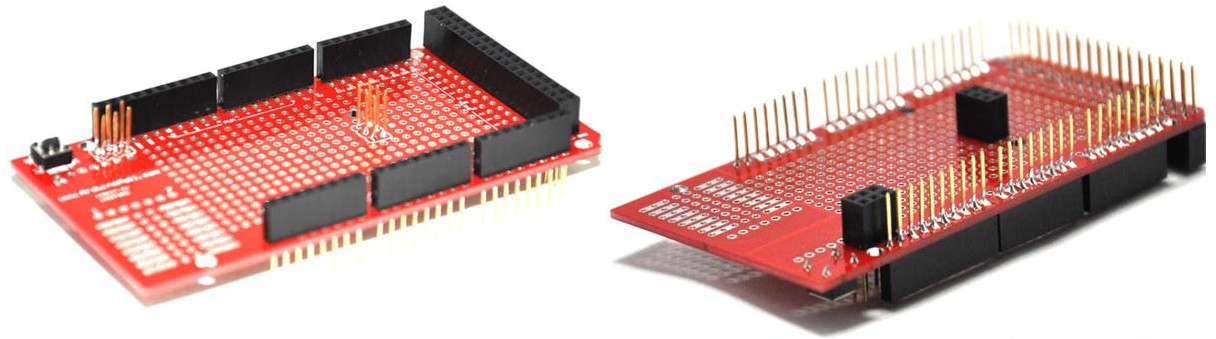
For prototype shield, please look to images available on topic about pat list.
http://www.ebay.com/itm/New-PCF8575-I2C ... 2599fcdc95
Add for your list 2 ULN2803 only.
For prototype shield, please look to images available on topic about pat list.
Post your doubts on forum because it can help another user too. Just PM me for support if it's absolutely necessary.
Post Number:#8
Sat Mar 28, 2015 9:53 pm
Posts: 10
Topics: 2 Solve rating: 0 Joined: Thu Mar 26, 2015 3:59 pm Topics: 2
Age: 28 Gender: National Flag:
This module is ok.
http://www.ebay.com/itm/New-PCF8575-I2C ... 2599fcdc95
Add for your list 2 ULN2803 only.
For prototype shield, please look to images available on topic about part list.
http://www.ebay.com/itm/New-PCF8575-I2C ... 2599fcdc95
Add for your list 2 ULN2803 only.
For prototype shield, please look to images available on topic about part list.
1. A bit confused, do I need x1 or x2 PCF8575?
2. These are the closest things I can find to the relay board on the part list, but they have a reset button on them. Will any of these work?:
http://www.ebay.com/itm/like/3214996107 ... =82&chn=ps
http://www.hobbyking.com/hobbyking/stor ... hield.html
http://www.ebay.com/itm/Blue-Prototype- ... 4897.l4275
3. What MOSFET do I use with 700mA and 1000mA LDD drivers on this power supply?
Post Number:#9
Sun Mar 29, 2015 10:11 am
Posts: 1699
Topics: 38 Images: 301 Solve rating: 233 Joined: Mon Mar 03, 2014 5:59 pm Topics: 38
Age: 39 Location: São Paulo Gender: National Flag:
Hi!
1 - Only one PCF8575.
2 - This models are too much different!

3 - The MOSFET isn't needed if you will use the LDD. Moreover the model is very clear on schematic (IRLZ44N).
Check it: viewtopic.php?f=25&t=218
Best regards.
1 - Only one PCF8575.
2 - This models are too much different!
3 - The MOSFET isn't needed if you will use the LDD. Moreover the model is very clear on schematic (IRLZ44N).
Check it: viewtopic.php?f=25&t=218
Best regards.
Post your doubts on forum because it can help another user too. Just PM me for support if it's absolutely necessary.
Post Number:#10
Sun Mar 29, 2015 6:10 pm
Posts: 10
Topics: 2 Solve rating: 0 Joined: Thu Mar 26, 2015 3:59 pm Topics: 2
Age: 28 Gender: National Flag:
Very helpful Fernando!
I think I found the protoshield finally. http://www.ebay.com/itm/181151830516?_mwbanner=1
A few more questions if that is OK:
1. Do I need a driver or MOSFET to use fans on PWM?
2. What power supply do I use with Ferduino?
3. What gauge wire do I use with the Ferduino?
4. Do you know the name of the plug used on RedTop's Ferduino? EDIT: I found it's DE-9 connector


5. Do I need any of these parts:
I think I found the protoshield finally. http://www.ebay.com/itm/181151830516?_mwbanner=1
A few more questions if that is OK:
1. Do I need a driver or MOSFET to use fans on PWM?
2. What power supply do I use with Ferduino?
3. What gauge wire do I use with the Ferduino?
4. Do you know the name of the plug used on RedTop's Ferduino? EDIT: I found it's DE-9 connector
5. Do I need any of these parts:
Ferduino Description wrote:
9 Jack phone 3.5 mm (6 are connected in analog pins and has pull up resistor of 10K and LEDs in parallel to be used with float switches, 3 are connected to a digital pin and has a resistor pull up of 4.7K Ohm to be used with temperature sensors in parasite mode);
2 Jack RJ45 (1 connected in an ULN2003 that’s controlled by analog pins, this circuit allow control devices untill 50V / 500mA, 1 connected to 3 analog pins and 4 digital pins);
1 Header 2 x 20 connected to hex buffers that allow connect TFT’s of 3.3V directly;
1 Connector DB37 in parallel with the header 2 x 20 that allow connect TFT’s of 3.3V using a serial cable;
2 Jack RJ11 (1 connected to digital pins, GND and 5V);
1 LAN;
1 Connector DB25 (connected to 2 ULN2803 controlled by an expander I2C)
4 Connector BNC (connected to 4 sockets to be used with circuits from Atlas Scientific).
Post Number:#11
Mon Mar 30, 2015 9:38 am
Posts: 1699
Topics: 38 Images: 301 Solve rating: 233 Joined: Mon Mar 03, 2014 5:59 pm Topics: 38
Age: 39 Location: São Paulo Gender: National Flag:
Hi!
1 - You need look the circuits here: viewtopic.php?f=24&t=40
2 - Any voltage between 7 and 12 V.
3 - For control a cat5 is enough.
4 - The connector is DB9.
Best regards.
1 - You need look the circuits here: viewtopic.php?f=24&t=40
2 - Any voltage between 7 and 12 V.
3 - For control a cat5 is enough.
4 - The connector is DB9.
Best regards.
Post your doubts on forum because it can help another user too. Just PM me for support if it's absolutely necessary.
Post Number:#12
Thu Apr 02, 2015 4:44 pm
Posts: 10
Topics: 2 Solve rating: 0 Joined: Thu Mar 26, 2015 3:59 pm Topics: 2
Age: 28 Gender: National Flag:
1. Instead of using a DB9 connector, is it OK to use Cat5 cords joined via coupler?
(Arduino PWM --> Cat5 cord --> coupler --> Cat5 cord --> LED, fan, etc.)
2. Is this the right ULN2803?
3. Do I need this:
4. Is this Mega OK?
(Arduino PWM --> Cat5 cord --> coupler --> Cat5 cord --> LED, fan, etc.)
2. Is this the right ULN2803?
3. Do I need this:
Ferduino Mega Description wrote:
1 Connector DB25 (connected to 2 ULN2803 controlled by an expander I2C)
4. Is this Mega OK?
Post Number:#13
Fri Apr 03, 2015 1:33 pm
Posts: 1699
Topics: 38 Images: 301 Solve rating: 233 Joined: Mon Mar 03, 2014 5:59 pm Topics: 38
Age: 39 Location: São Paulo Gender: National Flag:
Hi!
1 - As I told before use the best system for you;
2 - Yes;
3 - Vide 1;
4 - Yes.
Look to examples available on this forum: http://www.ferduino.com/forum/viewforum.php?f=18
Best regards.
1 - As I told before use the best system for you;
2 - Yes;
3 - Vide 1;
4 - Yes.
Look to examples available on this forum: http://www.ferduino.com/forum/viewforum.php?f=18
Best regards.
Post your doubts on forum because it can help another user too. Just PM me for support if it's absolutely necessary.
Post Number:#14
Fri Apr 03, 2015 9:25 pm
Posts: 10
Topics: 2 Solve rating: 0 Joined: Thu Mar 26, 2015 3:59 pm Topics: 2
Age: 28 Gender: National Flag:
Hi!
1 - As I told before use the best system for you;
2 - Yes;
3 - Vide 1;
4 - Yes.
Look to examples available on this forum: viewforum.php?f=18
Best regards.
1 - As I told before use the best system for you;
2 - Yes;
3 - Vide 1;
4 - Yes.
Look to examples available on this forum: viewforum.php?f=18
Best regards.
Many thanks Fernando. I will start a "Show your controller" thread when my parts arrive.
14 posts
• Page 1 of 1
Return to DIY Ferduino controller
Who is online
Users viewing this topic: No registered users and 1 guest